

How Highly Accelerated Life Testing and Highly Accelerated Stress Screening find design weaknesses and manufacturing defects — from step-stress profiles and 6-DoF repetitive-shock vibration to proof of screen and HASA.
Key takeaways
- HALT is a design-stage discovery test that steps stress far beyond specification to find weaknesses and measure operating and destruct limits — it is not a pass/fail qualification test.
- HASS is a production screen derived from HALT limits that precipitates and detects latent manufacturing defects on 100% of units without consuming meaningful product life.
- Both use 6-DoF repetitive-shock vibration (10 Hz–10 kHz, controlled in GRMS) combined with rapid thermal cycling of 60 °C/min or faster.
- A complete HALT typically needs 4–8 units and 3–5 days; a HASS screen runs in minutes to a couple of hours per unit.
- The value is realized in the follow-through: root-cause analysis, corrective action, and verification HALT — and, for HASS, a documented proof of screen.
1. Quick Reference
This first section is a condensed overview for readers who need the essentials quickly; the rest of the guide develops each topic in full.
What is HALT testing — and what is HASS?
HALT (Highly Accelerated Life Testing) is a discovery test used during design and development. Progressively increasing thermal, vibration, and combined stresses are applied to a small number of prototypes — well beyond specification levels — to find the weakest links in the design, establish its operating and destruct limits, and drive corrective action. HALT is not a pass/fail qualification test and does not simulate the field environment; its purpose is to precipitate failures quickly so they can be fixed before release.
HASS (Highly Accelerated Stress Screening) is a production screen derived from HALT results. Every unit (100% screening) is subjected to a short, aggressive stress profile — above specification levels but below the operating limits found in HALT — to precipitate and detect latent manufacturing defects before shipment, without consuming meaningful product life. Once the process is stable, HASS may transition to HASA (Highly Accelerated Stress Audit), which screens a statistical sample rather than every unit.
Key definitions
| Term | Definition |
|---|---|
| HALT | Highly Accelerated Life Test — design-stage step-stress test to discover design weaknesses and margins. |
| HASS | Highly Accelerated Stress Screen — production screen (100% of units) derived from HALT limits. |
| HASA | Highly Accelerated Stress Audit — HASS applied to a statistical sample of production. |
| LOL / UOL | Lower / Upper Operating Limit — stress level beyond which the product stops functioning correctly but recovers when stress is reduced (a soft-failure boundary). |
| LDL / UDL | Lower / Upper Destruct Limit — stress level at which permanent (hard) damage occurs; the product does not recover. |
| Operating margin | Difference between the specification limit and the operating limit. |
| Destruct margin | Difference between the operating limit and the destruct limit. |
| FLT | Fundamental Limit of Technology — the limit imposed by an intrinsic material property (e.g., solder melting point) that cannot be improved by design changes. |
| Precipitation screen | Higher-stress HASS segment, run above specification but below the HALT operating limits, to turn latent defects into detectable ones. |
| Detection screen | Lower-stress HASS segment, also below the operating limits, with the product powered and monitored, to detect the precipitated defects. |
| Proof of Screen (POS) | Demonstration that the HASS profile finds defects (effectiveness) and does not consume significant product life (safety). |
| Repetitive shock (RS) vibration | Six-degree-of-freedom, broadband pseudo-random vibration produced by pneumatic hammers on a HALT/HASS table. |
| Tickle vibration | Low-level vibration (~3–5 GRMS) applied intermittently during monitoring, because high vibration levels can mask intermittent defects. |
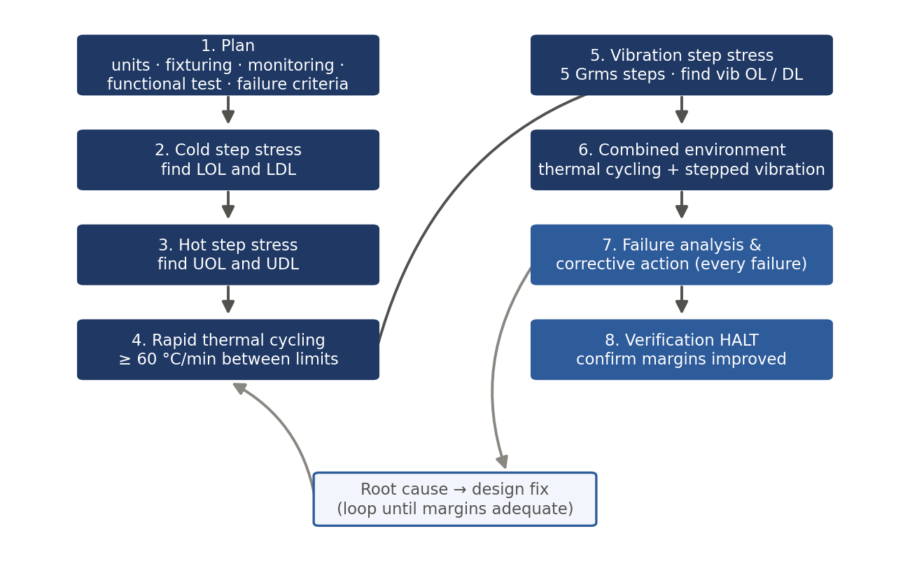
HALT test flow at a glance
- Cold step stress — lower temperature in steps (typically 10 °C) with dwells; find lower operating and destruct limits.
- Hot step stress — raise temperature in steps; find upper operating and destruct limits.
- Rapid thermal cycling — cycle between the limits found above at the fastest achievable ramp rate (typically 60 °C/min or faster).
- Vibration step stress — increase repetitive-shock vibration in steps (typically 5 GRMS) with dwells; find vibration operating and destruct limits.
- Combined environment — simultaneous rapid thermal cycling and stepped vibration; typically precipitates failures that neither stress finds alone.
- Failure analysis and corrective action for every relevant failure, then verification HALT to confirm margin improvement.
Typical stress parameters
| Parameter | Typical HALT practice | Typical HASS practice |
|---|---|---|
| Sample size | 4–8 units (minimum ~3 for confidence) | 100% of production (HASS) or sample (HASA) |
| Temperature steps | 10 °C steps; 10 min dwell after stabilization | Fixed profile derived from HALT limits |
| Thermal range | To destruct limits (product destruct limits often fall around −80 to +140 °C) | Inside HALT operating limits, reduced margin (a common starting point is ~80% of the operating-limit range) |
| Ramp rate | ≥ 60 °C/min product-level, as fast as achievable | Same chamber capability; 2–5 cycles typical |
| Vibration steps | 5 GRMS steps; 10 min dwells; to destruct limit | Below the vibration operating limit, above the specification level |
| Vibration type | 6-DoF repetitive shock, 10 Hz to 10 kHz | Same, at fixed screen level |
| Duration | 3–5 days per HALT (per assembly) | Minutes to ~1–2 hours per unit |
| Monitoring | Continuous functional test and monitoring throughout | Continuous monitoring during detection screen |
The single most important rule. A HALT failure at a stress level far beyond specification is not "unrealistic." The weakest link found under exaggerated stress is almost always the same weakest link that fails in the field under normal stress — accelerated stress simply compresses the time to reach it. Every relevant failure deserves root-cause analysis and a deliberate decision: fix it, or document why not.
2. How Is HALT Different from Traditional Qualification Testing?
Classical qualification testing (e.g., MIL-STD-810, IEC 60068) applies stresses that simulate the expected field environment, with margins, and asks a pass/fail question: does the product survive its specified environment? HALT asks a different question: where does the product break, and why? The two are complementary, not interchangeable — HALT does not replace compliance or qualification testing, and qualification testing rarely discovers design weaknesses efficiently.
| Aspect | Traditional qualification | HALT |
|---|---|---|
| Objective | Demonstrate compliance to specification | Discover weaknesses and design margins |
| Stress levels | At or modestly above specification | Stepped to operating and destruct limits |
| Outcome | Pass / fail | Ranked list of weaknesses; measured limits |
| Failures | Undesirable; may end the test | Expected and desired; the point of the test |
| Vibration | Single-axis ED shaker, controlled PSD | 6-DoF repetitive shock, broadband |
| Duration | Days to weeks per axis/stress | Typically 3–5 days total |
| When | Late design / pre-production | As early as functional prototypes exist |
Why does testing beyond specification work?
Most field failures in electronic and electromechanical products originate from a small number of latent weaknesses: fatigue-prone solder joints, inadequately restrained components, connectors and fasteners that loosen, resonant structures, marginal timing or thermal design. Elevated stress accelerates the mechanisms that expose these weaknesses — fatigue accumulates with stress amplitude raised to a large exponent, so a modest increase in stress produces an enormous reduction in time-to-failure. HALT exploits this: the order in which weaknesses appear under accelerated stress generally matches their order of appearance in the field.
Two consequences follow. First, HALT results are qualitative and comparative, not a quantitative life prediction — HALT does not by itself produce an MTBF number. Second, increasing the margin between specification and operating/destruct limits is the mechanism by which HALT improves field reliability: larger margins mean the field stress distribution rarely reaches the failure threshold.
Where HALT and HASS fit in the product lifecycle
- Design/development: HALT on early prototypes and again on design-mature units. The earlier weaknesses are found, the cheaper they are to fix.
- Design verification: verification HALT after corrective actions confirms margins improved and no new weaknesses were introduced.
- Production ramp: HASS profile developed from HALT limits, validated by proof of screen, applied 100%.
- Mature production: transition to HASA (audit sampling) when defect rates are demonstrably low and stable; return to 100% HASS on process changes, vendor changes, or defect excursions.
- Sustaining: repeat HALT for significant design changes, component substitutions, or new suppliers of critical parts.
3. Equipment and Stress Types
The HALT/HASS chamber
HALT and HASS are performed in a combined-environment chamber that provides rapid thermal cycling and repetitive-shock vibration simultaneously. Key characteristics:
- Thermal system: liquid-nitrogen (LN2) cooling and high-power electric heating, giving product-level ramp rates of 60 °C/min or more and typical air temperature range of approximately −100 °C to +200 °C.
- Vibration table: an aluminum or magnesium table driven by an array of pneumatic impact hammers mounted at angles on its underside.
- Control: thermal control via product-mounted thermocouples (control on product response, not just air); vibration set-point in overall GRMS measured by table or product accelerometers.
What vibration type is used in HALT and HASS testing?
The vibration used in HALT and HASS is repetitive-shock, six-degree-of-freedom pseudo-random vibration. Pneumatic hammers repeatedly strike the table, exciting it simultaneously in three translational axes (X, Y, Z) and three rotational axes (roll, pitch, yaw). The result is broadband excitation from 10 Hz to 10 kHz, so essentially every structural resonance of the product is excited at once, in every orientation, without changing fixtures.
The spectrum is not a controlled, flat PSD: it is determined by the table structure, hammer pressure, and fixturing, and its energy distribution is non-Gaussian with substantial high-frequency content. Control is therefore by overall GRMS level rather than by a shaped spectral profile. Because the spectral content differs fundamentally from electrodynamic-shaker random vibration, GRMS values from a HALT table are not directly comparable to GRMS values from an ED shaker test, and HALT vibration levels cannot be mapped onto MIL-STD-810 or similar profiles.
Why repetitive shock rather than an ED shaker? A single-axis electrodynamic shaker excites resonances only along one axis at a time and typically rolls off by 2–3 kHz. Six-DoF repetitive shock excites all axes and rotations simultaneously across a wider band, which precipitates fatigue- and loosening-type defects far faster — the objective of HALT/HASS — at the cost of precise spectral control, which HALT/HASS does not need.
Tickle vibration
High vibration levels can mask intermittent failures — a cracked solder joint may make contact intermittently at 30 GRMS yet open cleanly at 5 GRMS. Standard practice is therefore to periodically drop to a low "tickle" level (~3–5 GRMS) during and after high-level dwells, while running functional tests, and to monitor continuously through the transitions. Many intermittent defects are detectable only in this low-level window.
Thermal stress
- Cold and hot steady-state: step stressing to find operating and destruct limits in each direction. Dwell at each step until the product (not the air) stabilizes, then hold typically 10 minutes with functional testing.
- Rapid thermal cycling: transitions at the maximum achievable product-level rate (≥ 60 °C/min typical) between levels somewhat inside the discovered limits. This stresses interfaces with mismatched coefficients of thermal expansion — solder joints, plated through-holes, bonded structures — far more effectively than slow cycling.
Combined environment
Simultaneous rapid thermal cycling and vibration is the most effective precipitation environment available; the two stresses interact (e.g., cold-embrittled materials under vibration; thermally expanded assemblies under shear) and routinely expose weaknesses that neither stress finds alone. The combined-environment segment is normally the final and most productive stage of HALT, and it is the basis of the HASS precipitation screen.
Other applied stresses
Thermal and vibration are the core HALT stresses, but a thorough HALT also exercises the product electrically. Common additional stresses, selected by relevance to the product: power cycling (including power-up at temperature extremes), voltage margining (supply stepped above and below nominal at stress extremes), frequency margining where the design permits, load variation across and beyond the specified range, and humidity, DC bias, or product-specific stresses where the failure physics warrant them.
4. HALT Methodology
4.1 Planning and preparation
Test units
Use 4–8 functional units representative of the design under evaluation; three is a practical minimum for distinguishing a design weakness from a workmanship escape. Early engineering prototypes are acceptable — finding problems early is the point — but record configuration precisely so results can be tied to a design revision. Retain failed hardware for failure analysis.
Fixturing
The fixture must transmit table energy into the product efficiently and stiffly: machined aluminum plates or brackets bolted directly to the table, clamping the product as it is mounted in service where practical. Verify transmissibility with accelerometers on the product; a soft fixture that attenuates input invalidates vibration levels. Orientation changes are generally unnecessary given 6-DoF excitation, but products with strong directional structure may warrant a second orientation.
Instrumentation and monitoring
- Thermocouples on thermally significant locations (hottest component, largest mass, control point). Control the chamber from a product thermocouple.
- Accelerometers on the table and at representative product locations.
- Continuous functional monitoring — the product must be operating and exercised throughout the test. A comprehensive, fast, automated functional test is the single biggest determinant of HALT quality: undetected failures are unlearned lessons.
- Data logging of all monitored parameters with timestamps correlated to the stress profile.
Failure criteria
Define in advance what constitutes a soft failure (recoverable malfunction — the basis of operating limits) and a hard failure (permanent damage — the basis of destruct limits), and what functional degradation counts as failure for this product.
4.2 Cold and hot step stress
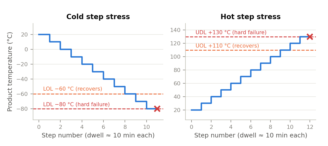
Begin at ambient (or the lower specification limit) and decrease temperature in 10 °C steps. At each step, allow the product temperature to stabilize, dwell approximately 10 minutes, and run the full functional test with power cycling. Continue past the point of soft failure (the lower operating limit, LOL) — verify recovery by warming — and onward until a hard failure establishes the lower destruct limit (LDL), or until the fundamental limit of technology or chamber capability is reached.
Then repeat the procedure upward in 10 °C steps from ambient. Identify the upper operating limit (UOL) where the product malfunctions but recovers on cooling, then continue to the upper destruct limit (UDL). Hot-side limits are often set by component ratings or software/thermal shutdowns; where a deliberate shutdown intervenes, record it as such and consider testing beyond it where safe and informative.
4.3 Rapid thermal cycling
Cycle between temperatures a safe margin inside the discovered operating limits (commonly 5–10 °C inside), at the maximum achievable ramp rate, for a small number of cycles (typically 3–5 in HALT). The product operates and is monitored throughout, with functional tests during ramps as well as at dwells — many defects appear only during transitions. Thermal cycling exposes CTE-mismatch and fatigue mechanisms that steady-state stepping does not.
4.4 Vibration step stress
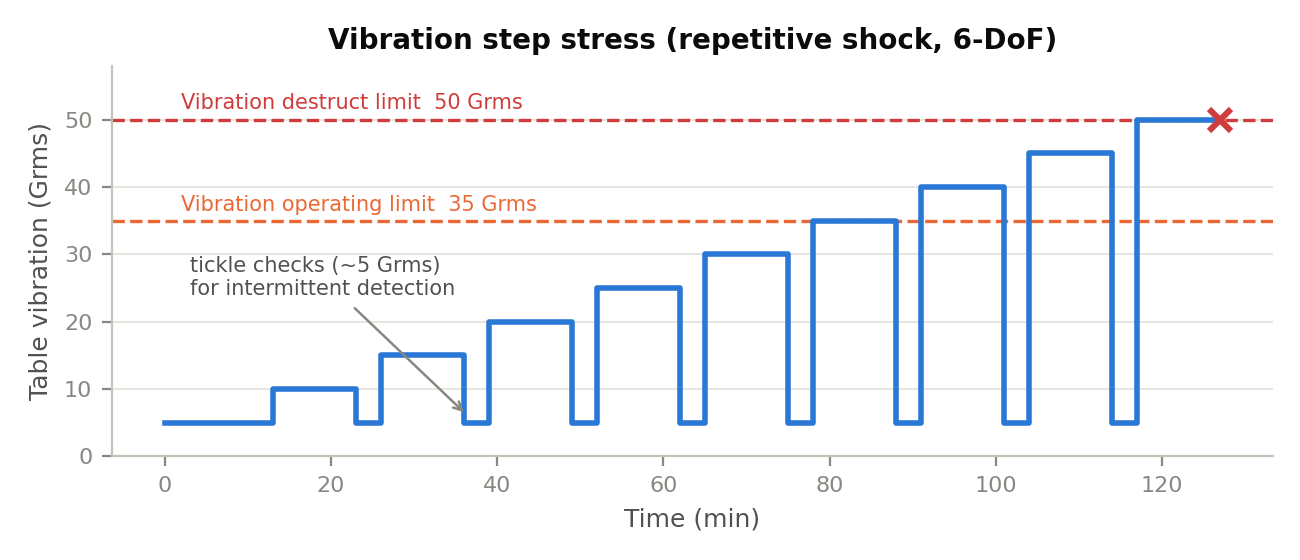
At benign temperature, apply repetitive-shock vibration starting at approximately 5 GRMS and increase in 5 GRMS steps with ~10 minute dwells and continuous functional testing. Include tickle-level checks after each high-level dwell to catch masked intermittents. Continue past the vibration operating limit to the vibration destruct limit. After each step, inspect for mechanical damage: fastener back-out, component lead fractures, cracked joints, chafed wiring. Note that some fatigue damage is cumulative; when the destruct level is reached, attribute failures with cumulative exposure in mind.
4.5 Combined environment
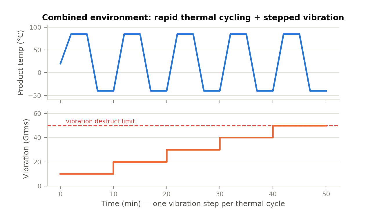
Run simultaneous rapid thermal cycling and vibration. A standard profile steps vibration upward with each successive thermal cycle (e.g., five thermal cycles with vibration at 1/5, 2/5, 3/5, 4/5, and 5/5 of the vibration destruct limit), with dwell durations from the individual-stress segments and continuous monitoring plus tickle checks. New failures at combinations of stresses each individually survivable are common and are precisely the failures this segment exists to find.
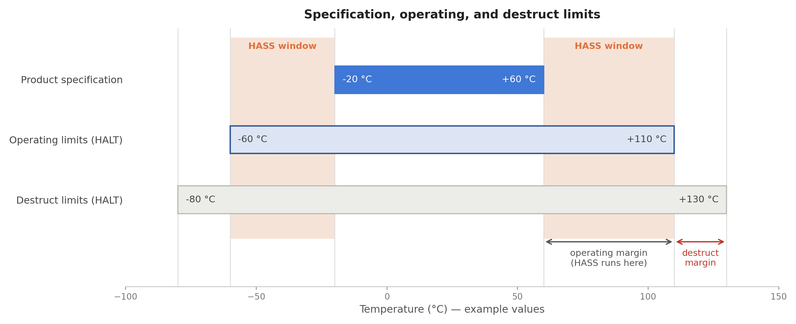
4.6 Limits, margins, and what to do with them
The product of HALT is a set of measured limits and the failures behind them. Operating limits (soft failures — the product recovers when stress is removed) become the upper bound of the HASS screen — precipitation and detection both run below them and above specification — and the basis of margin assessment against specification. Destruct limits (hard failures — permanent damage) are a metric of design robustness and show how much margin lies beyond the screen.
Judge each margin against the specification and the field environment. There is no universal required margin, but common practice looks for operating limits comfortably beyond specification (e.g., ≥ 20 °C thermal, and substantial vibration margin) and treats any weakness inside or near specification as mandatory to fix. Where a limit is set by the fundamental limit of the technology, document it and stop; where it is set by a fixable weakness, fix it.
4.7 Failure analysis and corrective action
- Log every anomaly with the stress conditions at occurrence, whether it recovered, and the affected function.
- Perform root-cause failure analysis on each relevant failure down to the physical mechanism (fatigue, overstress, contamination, timing margin, etc.).
- Classify: design weakness, workmanship/process escape, component defect, test-induced artifact, or fundamental limit of technology.
- Disposition every finding explicitly — corrective action with owner and due date, or a documented, justified decision to accept.
- Run verification HALT on corrected hardware to confirm the weakness is eliminated, margins improved, and no new weaknesses were introduced.
Discipline point. A HALT without disciplined failure analysis and closed-loop corrective action is an expensive way to break prototypes. The chamber time is the cheap part of the program; the engineering follow-through is where reliability is actually gained.
4.8 HALT reporting
A HALT report should contain, at minimum: product configuration and serial numbers; fixture and instrumentation description; the as-run stress profiles; all limits found (tabulated, with the failing item for each); every failure with root cause and disposition; margin assessment against specification; and recommendations, including whether the design is ready for HASS development. Photographs of fixturing and failures materially improve the report's long-term value.
5. HASS Methodology
5.1 Purpose and preconditions
HASS finds latent manufacturing defects — cold solder joints, cracked components, loose hardware, workmanship and process escapes — in production units, quickly enough and gently enough to be run on 100% of product. HASS presupposes a HALT-matured design: screen levels live in the operating margin — above specification, below the operating limits — so a design with thin operating margins cannot be screened effectively. Do not attempt HASS development until HALT corrective actions are complete and margins are adequate.
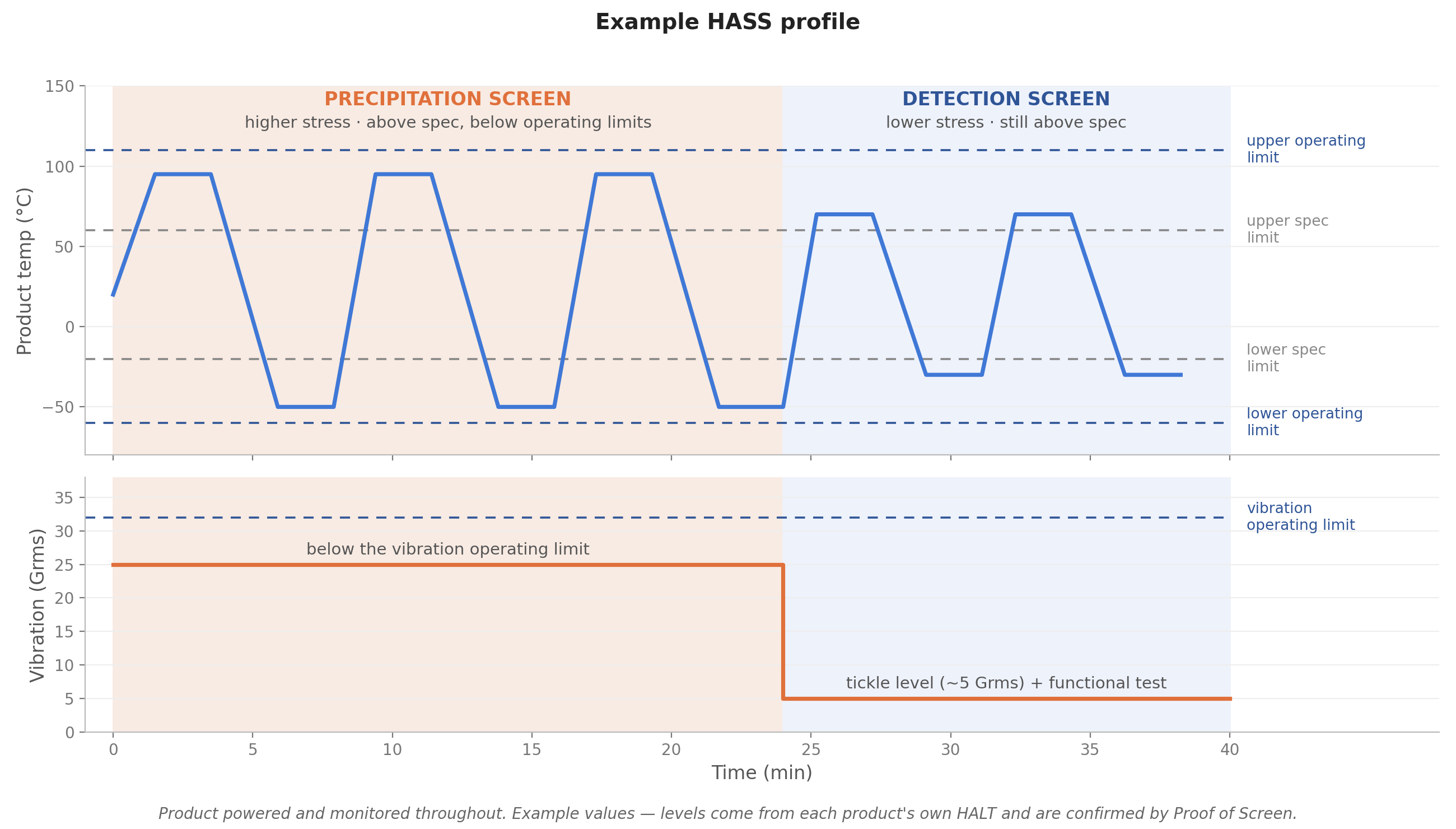
5.2 Screen structure: precipitation and detection
- Precipitation screen: the higher-stress segment, above specification but below the operating limits, applied to convert latent defects into patent (detectable) ones. Because it stays inside the operating limits, the product can be powered and monitored during precipitation as well. Combined thermal cycling and vibration is the normal precipitation environment.
- Detection screen: lower stress, still within the operating limits, with the product powered, exercised, and continuously monitored, so that precipitated defects are actually observed. Includes tickle vibration and functional testing through thermal transitions.
A typical HASS profile is a small number of combined-environment cycles (often 2–5) with a precipitation segment followed by a detection segment, totaling minutes to a couple of hours per unit.
5.3 Setting initial screen levels
Industry rules of thumb for an initial profile, always subject to tuning and proof of screen:
| Stress | Initial precipitation level | Initial detection level |
|---|---|---|
| Thermal | Above specification, below the HALT operating limits by a safety margin (a common starting point is ~80% of the operating-limit range) | Inside operating limits by a comfortable margin (e.g., 5–10 °C) |
| Vibration | Below the vibration operating limit, above the specification level | Tickle level (~3–5 GRMS) during functional test |
| Ramp rate | Maximum achievable | Maximum achievable |
These are starting points, not requirements: the correct screen is the one validated by proof of screen for this product, this process, and this failure history.
5.4 Proof of Screen (POS)
Before production use, the candidate profile must be shown to be both effective and safe:
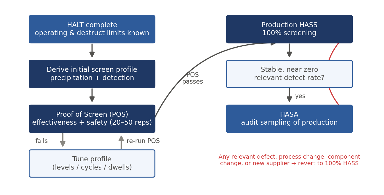
- Effectiveness: the screen finds defects. Demonstrate by screening units with known or seeded defects (e.g., deliberately marginal joints, loosened hardware) or by confirming it catches defect types from the current escape history.
- Safety (life consumption): the screen does not meaningfully consume product life. Demonstrate by running a small set of units through many consecutive screens — 20 to 50 repetitions is common practice — with full functional verification; survival with margin indicates a single screen consumes a small fraction of life. Follow with a HALT on screened vs. unscreened units where practical to confirm limits have not degraded.
Document the POS results as the baseline authorization for the production screen, and repeat POS when the screen or the design changes materially.
5.5 Running HASS in production
- Screen 100% of units; disposition every failure with root cause and corrective action into the production process — HASS is a process-improvement engine, not just a filter.
- Trend yield and defect Pareto weekly; a rising precipitation rate signals a process or supplier excursion.
- Keep fixtures, profiles, and monitoring under configuration control; requalify the screen (POS) after design or process changes.
- Feed systemic findings back to design and to HALT: recurring HASS failures of one mechanism may indicate thin margin, not just workmanship.
5.6 Transition to HASA
When HASS yield is high and stable — typically after sustained near-zero relevant defect rates — the screen may move to an audit basis (HASA), screening a statistical sample per lot or per period. Define the sampling plan, the escape-risk basis for it, and, critically, the trigger conditions for reverting to 100% HASS: any relevant defect found in audit, process or component changes, new suppliers, or field-return signals.
6. Program Management Considerations
When HALT/HASS is (and is not) the right tool
- Best suited to electronics and electromechanical assemblies where fatigue, interconnect, and workmanship mechanisms dominate field failures.
- Less suited to failure mechanisms that accelerated thermal/vibration stress does not excite: wear-out of consumables, corrosion, electromigration, optical degradation — cover these with targeted life tests.
- HALT results are design-comparative, not predictive: they do not produce MTBF numbers and do not replace reliability prediction, demonstration, or compliance testing.
- Very large or very high-mass products may exceed table capability; HALT subassemblies in that case.
Cost–benefit profile
A HALT typically costs a few prototypes and less than a week of chamber time, positioned at the point in development where design changes are cheapest. Its return is avoided field failures, warranty cost, and redesign spins. HASS adds per-unit production cost (minutes of chamber time and monitoring) and is justified where field-failure cost is high, processes are immature, or volumes make early defect detection valuable; HASA preserves most of the benefit at a fraction of the cost once stability is proven.
Common pitfalls
- Weak functional test coverage during test — failures precipitate but go undetected.
- Soft fixturing that attenuates vibration input, silently invalidating levels.
- Stopping at the first failure instead of continuing to find the next weakest link.
- Dismissing high-stress failures as unrealistic rather than analyzing them.
- Running HASS with thin margins, consuming product life or damaging good units.
- Treating HALT as a pass/fail gate — it is a discovery process; a "pass" with no findings usually means the stresses or monitoring were inadequate.
- No closed-loop corrective action, or no verification HALT after fixes.
7. Standards and Further Reading
| Document | Scope |
|---|---|
| IEST-RP-PR003, "HALT and HASS" | The principal industry recommended practice dedicated to HALT and HASS methodology (Institute of Environmental Sciences and Technology). |
| IPC-9592B | Requirements for power conversion devices; formally incorporates HALT and HASS requirements and profiles for that product class. |
| IEC 62506, "Methods for product accelerated testing" | International standard covering accelerated test methods, including qualitative accelerated testing of the HALT type. |
| MIL-HDBK-2164 / legacy ESS documents | Classical environmental stress screening background; useful contrast to HASS practice. |
Which standards call for HALT and HASS, and which are qualification tests instead, is set out standard by standard in our HALT/HASS standards guide.
Reference books: Gregg K. Hobbs, Accelerated Reliability Engineering: HALT and HASS (the foundational text by the originator of the methods); Harry W. McLean, HALT, HASS, and HASA Explained: Accelerated Reliability Techniques (ASQ Quality Press); Kirk A. Gray and John J. Paschkewitz, Next Generation HALT and HASS: Robust Design of Electronics and Systems (Wiley).